- Home
- About Us
- Products
- VentSaver Instructions
- SS Ventsaver Panel Matrix
- Contact
VentSaver Vent Guards Installation Instructions:
These installation guidelines are provided as assistance to installers with commercial and residental sites. VentSaver.com takes no responsibility for errors or omissions and cannot be held responsible for product installation.VentSaver FB-151 Installation Method |
|||
Mount VentSaver FB-151 in 3 Easy Steps: |
|||
| Recommended Tools: Cordless drill with 5/16" driver, tin snips, two 7/16" wrenches, caulk gun | |||
 |
|||
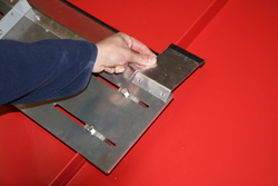
| 1. Attach FIN to BASE ANGLE
Assemble with two 1/4" X 3/4" S.S. bolts. NOTE: In case of rib obstruction, base angle is reversible. |
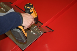
2. Base Installation: Put sealant on bottom of base angle. Place Ventsaver centered behind pipe and fasten base to roof with the four 1 1/2" lag screws. | 3. Strap Installation: Put 1/4" X 3/4" bolt through the bent end of the strap. Install as illustrated in TOP VIEW. Cut off excess strap. For vent pipes cut pipe off 2" to 3" above the Ventsaver. | |
| Check all fasteners for tightness! | |||
VentSaver P-383 Installation Method |
|||
Mount VentSaver P-383 in 3 Easy Steps: |
|||
| Recommended Tools: Cordless drill with 5/16" driver, tin snips, two 7/16" wrenches, caulk gun | |||
 |
|||
| 1. Attach FIN to BASE ANGLE
Assemble with two 1/4" X 3/4" S.S. bolts. NOTE: In case of rib obstruction, base angle is reversible. |
2.
Base Installation: Put sealant on bottom of base angle. Place cable over chimney
or vent with Ventsaver centered behind and close to pipe. Fasten base
to roof with
the four 1
1/2" lag
screws. Note: If unable to fit the cable over the top of the pipe, detach the cable eye by removing the nut. Wrap the cable around the pipe and reassemble tightly. |
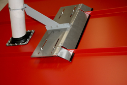
3. Pull on cable end with pliers until snug.
Keep shoulder strap on the opposite side of teh pipe from the Ventsaver.
Tighten nut and bolt firmly. Trim Excess cable. Note: For smaller applications, cut and remove stainless steel shoulder strap attached to cable. |
|
| Check all fasteners for tightness! | |||
VentSaver HD Installation Method |
|||
Mount VentSaver HD in 4 Easy Steps: |
|||
| Recommended Tools: Cordless drill with 5/16" driver, tin snips, two 7/16" wrenches, caulk gun | |||
 |
|||
1. Attach FIN to BASE ANGLE
|
2. Base Installation: Place cable over chimney
or vent with Ventsaver centered behind and close to pipe. Fasten base
to roof with
the four 1
1/2" lag
screws. |
||
3. Pull on cable end with pliers until snug.
Keep shoulder strap on the opposite side of teh pipe from the Ventsaver.
Tighten nut and bolt firmly. Trim Excess cable. |
4. Install Snow Diverter Wing Kit (Optional)
|
||
| Check all fasteners for tightness! | |||
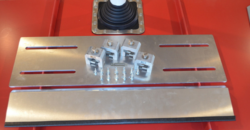
Standing Seam Ventsaver Kit |
|||
|
This kit includes: (1) ¼" Adjustable Aluminum Plate 19"
or 27" wide (1) 1/8" aluminum Ice Ramp w/ edging
strip (4) RCT universal fit standing seam
clamps (12) Tek screws ¼" x 1" 3/8" hex head (12) Set screws for the clamps 3/16"
hex/allen drive (4) 9/16" hex RCT top bolts with
stainless washers (1) 3/16" hex bit for set screw
tightening Ventsaver kit includes Fin, Base
Angle, (2) ¼" x ¾" s.s. bolts with (2) lock nuts, steel cable, 2 cable locks
with 5/16" nuts.
Tools Needed for Installation Safety Goggles and Gloves Wax or Lead Pencil to mark clamp
location Ratcheting Torque Wrench (capable of
reading in in/lbs) Tape Measure 9/16" Socket 7/16" Socket or wrench 3/8" Socket 1/8" Drill Bit Screw Gun or Impact Driver Adjustable Wrench Hand Grinder , Hacksaw, or Sawzall
with metal blade The SS VentSaver Kit is available in two sizes. Model 12-16 fits seams 12"
to 16" wide. This is the best option if
your seams are 16" or less in width in order to avoid excessive overhang.
Model 12-24 fits all seams
from 12" to 24" wide. This universal fit
bracket is best used with seams wider than 16", but has the ability to span
across two 12" wide seams if needed.
This is a good option for contractors that need a universal fit device
in stock. Installation Procedure Prior to installation, read and fully
understand all steps required for the SS Ventsaver bracket AND for the Ventsaver
device being attached to the pipe. 1.
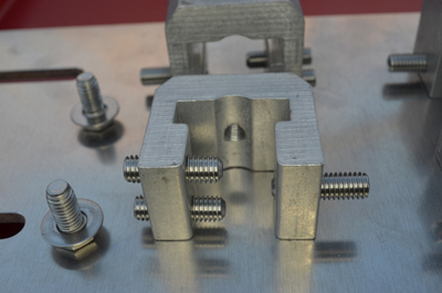
Load all 12 set
screws into the RCT clamps with the cupped tips pointing inwards and the female
hex end pointing outwards. Keep the
single set screw flush and the 2 adjacent set screws evenly spaced so that the
clamps install straight.
2.
Attach the 4
clamps to the Adjustable Aluminum Plate using the top bolts and washers. Clamps should be loose and able to slide side
to side in the bracket slots. Set onto seams just upslope of the pipe being
protected.
3.
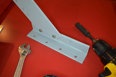
Assemble the Fin to
the Angle Base as shown below with two ¼" x ¾" S.S bolts with 7/16" wrench or
socket.
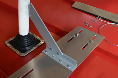
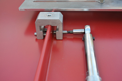
4.
Once assembled,
set it on the Adjustable Aluminum Plate so it is centered with the pipe located
down slope and just touching the tip of the Fin. Move the Adjustable Aluminum Plate up the
seam until the Base Angle is properly positioned and flush with the edge of the
Plate closest to the pipe. Mark the (4)
holes in the Base Angle and the location of all 4 RCT clamps on the seam. Pre-drill 4 pilot holes, with a 1/8" drill
bit, using the holes in the Base Angle as a guide. Make sure not to drill thru the roof panels. A small block of wood
temporarily slid underneath the plate works well. Before
running the screws in the plate, make sure the Tek Screws will not touch the
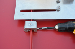
roof panel when tightened. Fasten Base Angle to Adjustable Aluminum Plate using
(4) Tek Screws, 3/8" bit, and a screw gun.
5.
Remove the RCT top
bolts and set the Adjustable Aluminum Plate/Ventsaver assembly aside. Using a 3/16" bit and screw gun or ratchet,
attach the clamps to the seams and set to 90 IN/LBS with a torque wrench
capable of reading IN/LBS. Hold steady
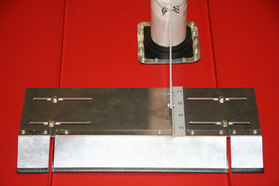
downward pressure on the clamps to be sure they stay flat and centered on the seam. 6.
Position the Adjustable
Aluminum Plate/VentSaver assembly over the clamps and reinstall the top bolts
and washers. Torque the top bolts to 90
IN/LBS. Regardless of where the pipe
protrudes through the panel, the Adjustable Aluminum Plate is always centered
on the seams with an equal overhang on both sides.
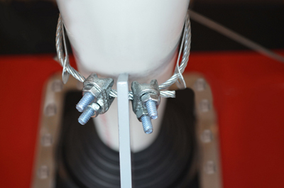
7.
Run the cable thru
the hole in the top of the Fin, around the pipe and back through the hole. Install a cable lock on either side of the Fin
as shown, being sure to lock both cables in each cable lock. Vice grips can be used to hold the cable
together while you install the cable locks using 5/16" socket and screw gun. Trim off or tuck in the excess cable.
The Next Step is Essential!
8.
Installing the Ice
Ramp This component is vital to keeping ice from sliding under the Adjustable
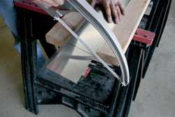
Aluminum Plate assembly and damaging the base of the pipe and/or the boot. The Ice Ramp needs to be custom cut to
properly fit your roof. A Sawzall with
metal blade, hand held angle grinder with cutoff blade, chop saw, or a simple
hacksaw can be used. Take precautions by using gloves and safety goggles to
protect yourself from injury while cutting and installing the Ice Ramp. Mark the location of the seams and be
sure to cut the center section about 1" narrower than the seams to avoid
scratching the panel. Fasten the center
piece of the Ice Ramp and 2 equal size end pieces to the upslope side of the Adjustable
Aluminum Plate, making sure the lip rests on the top of the plate. Use a 1/8" drill bit to pre-drill holes every
4" and fasten with Tek screws. Take
extra care to not drill through the plate into the panels. Use a temporary small
wood block, as previously done in step 4.
The Ice Ramp can be hand bent to allow for different seam heights. Be sure the edging is tightly in place and
that it rests on the panel when screwed down.
Some plate designs may require you to notch out for the end of the base
angle. This is easily done by
marking where the base angle will be and making two cuts 1" deep. Use pliers to
bend the cut section up, then use a hacksaw or grinder to remove the section.
The installation instructions above show
the pipe centered between the seams, but this isn't always the case. Regardless of where the pipe protrudes
between the seams, the Adjustable Plate is always centered on the seams with an
equal overhang on both sides. The Angle
Base can be fastened anywhere along the Adjustable Plate to accommodate the
location of the pipe. See Below for an
example of an off center pipe
|
|||
| Back to Top | |||
Warranty |
|||
| The following warranty is made in lieu of all other warranties expressed or implied. Recommendations for proper use of the product are based on tests believed to be reliable. Any goods proven to be defective due to materials will be replaced, or purchase price refunded, but in no event shall the manufacturer be responsible for damages in excess of the purchase price. User shall determine the suitability of the product for its intended use and assumes all risks of its use or handling. | |||